TM 9-2320-365-10
1-17. COOLING SYSTEM
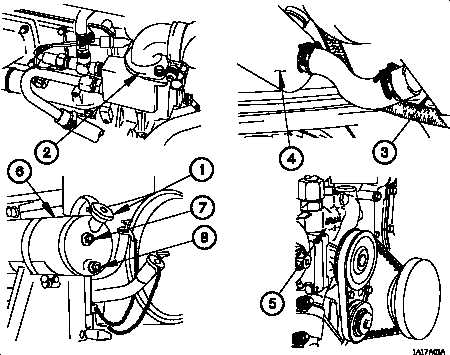
Figure 1-12. Cooling System
The Cooling System protects the engine, transmission, and air compressor by providing
a means of removing the heat generated during operation of the vehicle.
(1) The radiator pressure cap (1, Figure 1-12), in combination with the ethylene glycol-
based antifreeze, effectively raises the boiling point of the coolant to well above 212F
(100C).
(2) The thermostat (2) helps the engine to warm up quickly by remaining closed until
the coolant temperature reaches approximately 199F (93C).
When the coolant
temperature reaches approximately 199F (93C), the thermostat opens and coolant is
circulated through the water jacket in the engine to maintain the correct operating
temperature for the engine.
Coolant is drawn from the radiator (3), through the
transmission oil cooler (4), and circulated through the cooling system by the water pump
(5). Heat is drawn from the radiator by the engine fan pulling air over the radiator
cooling fins.
(3) A radiator overflow tank (6) is provided to allow for expansion of the coolant. The
radiator overflow tank also serves as the point where new coolant is introduced into the
cooling system. The radiator overflow tank has two sight glasses; the upper sight glass
(7) indicates the level to fill to with engine shut down. If coolant is not visible in the lower
sight glass (8), do not operate the vehicle.
1-37