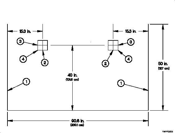
TM 9-2320-365-34-1D-7. HEADLIGHT ADJUSTMENT SCREENThe headlight adjustment screen may be drawn on any vertical surface at least 50 in. (1270 mm) high and 100 in. (2540mm) wide.a. Draw two vertical lines (1) 50 in. (1270 mm) high and 90.6 in. (2300 mm) apart (centered on headlight adjustmentscreen).b. Locate two points 40 in. (1016 mm) from floor and 15.3 in. (389 mm) toward the center from each vertical line (1).c. Draw vertical line (2) about 3-5 in. (76-127 mm) centered on each of the two points.d. Draw horizontal line (3) about 3-5 in. (76-127 mm) centered on each of the two points.e. Measure out 4 in. (102 mm) along each vertical line (2) and horizontal line (3) from each of the two points to make8 in. (203 mm) squares (4).Figure D-19. Headlight Adjustment ScreenD-8. LEFT FRONT LEAF SPRING U-BOLT SOCKETUse a 6-point 1-1/16 in. or 27 mm 3/4 in. drive impact socket. Grind down wrenching end to a maximum OD of 15 in.(38.3 mm) to fit rear inboard U-bolt nut on left front leaf spring. No modification is required if a6-point, thin wall, deep 27mm impact socket can be obtained.D-24
Integrated Publishing, Inc. - A (SDVOSB) Service Disabled Veteran Owned Small Business