TM 9-2320-365-34-1
Figure 1-15. Brake System (Cont)
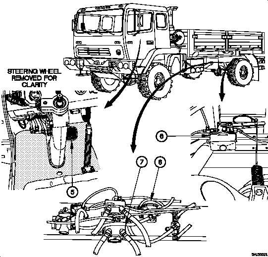
The foot control valve is operated by the brake pedal (5) and receives pressurized air from both the primary and
secondary air tanks. The foot control valve is a dual activation design, with one set of ports supplying air to the front
brakes from the secondary air tank and another set of ports supplying air to the rear brakes from the primary air tank.
The plumbing between the primary and secondary air tanks is designed to allow controlled braking in the event of a
failure in either the primary (rear brakes) or secondary (front brakes) brake circuit. Air from the foot control valve is
supplied to the load sensing valve (6) which, in turn, controls air delivery to the relay valve (7). The load sensing valve
is mounted on a crossmember and connected, by a spring and cable, to the rear axle. The arrangement of the load
sensing valve provides a mechanical anti-lock feature to the rear brakes by sending less air to the rear brakes when
the vehicle is not heavily loaded. The relay valve is used to provide the Operator with quicker brake response. An
inversion valve (8) redirects air from the secondary brake circuit to the primary brake circuit in case of loss of pressure
in the primary brake circuit. This feature allows control of the spring brakes and prevents early rear brake lock-up.
Change 1
1-21