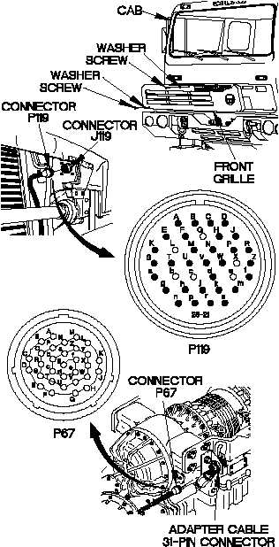
Change 1 2-631TM 9-2320-365-34-1WARNINGWear appropriate eye protection when workingunder vehicle due to the possibility of fallingdebris. Failure to comply may result in injuryto personnel.Ensure exhaust system is cool before performingtroubleshooting. Failure to comply may result ininjury to personnel.CAUTIONUse care when testing electrical connectors.Do not damage connector pins or socketswith multimeter probes. Failure to complymay result in damage to equipment.CONTINUITY TESTLoose or dirty connectors may causeintermittent loss of power to transmissionECU and diagnostic codes to be logged.Ensure that all connectors are clean and tightbefore performing troubleshooting. Failure tocomply may result in incorrect test results.NOTEInspect connector pins/sockets for damage,corrosion, and serviceability. Check thatconnector pins are not pushed back andare capable of making good contact.(1) Remove two screws and washers fromfront grille.(2) Remove screw and washer from frontgrille.(3) Remove front grille from cab.(4) Disconnect connector P119 fromconnector J119.(5) Disconnect connector P67 from adaptercable 31-pin connector.(6) Set multimeter to ohms.(7) Connect positive (+) probe of multimeterto connector P119-a.(8) Connect negative (-) probe of multimeter to connector P67-N and note reading on multimeter.(9) If continuity is not present, replacetransmission external wiring harness(para 6-7).(10) Connect positive (+) probe of multimeterto connector P119-a.CONTINUITY TEST (Cont)(11) Connect negative (-) probe of multimeterto all other pins in connector P119 andnote reading on multimeter.(12) Connect negative (-) probe of multimeterto ground and note reading on multimeter.(13) If continuity is present, transmissionexternal wiring harness is shorted; replacetransmission external wiring harness(para 6-7).
Integrated Publishing, Inc. - A (SDVOSB) Service Disabled Veteran Owned Small Business