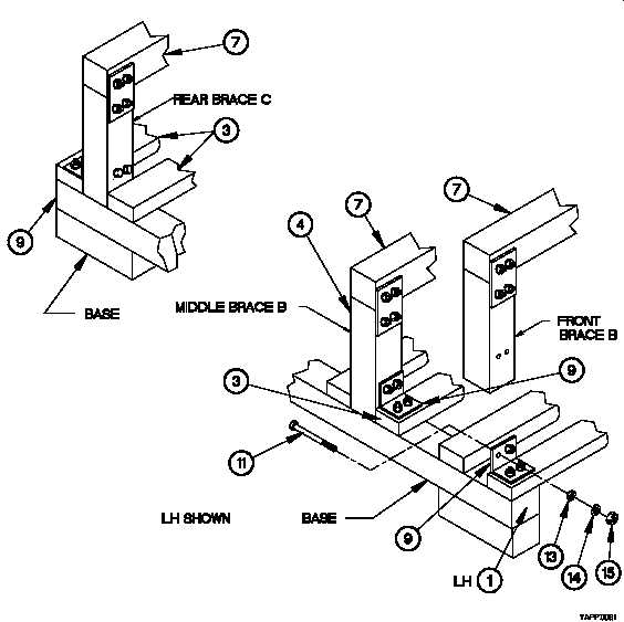
TM 9-2320-365-34-2Figure D-8. Cab Maintenance Stand Brace to Base Assemblyl. At left side of base (1) LH, place middle Brace B o n the base as shown inFigure D-8. Cab Maintenance StandBrace to Base Assembly.m. Using angle bracket (9) on base as a template, mark holes on Brace B and match drill 0.38 in. (9.6 mm) holethrough Brace B brace (4) as shown in Figure D-8. Cab Maintenance Stand Brace to Base Assembly.n. Secure Brace B t o base spreader (3) using 2 bolts (11), flat washers (13), lockwashers (14), and hex nuts (15).o. Repeat steps m-n for front Brace B.D-13
Integrated Publishing, Inc. - A (SDVOSB) Service Disabled Veteran Owned Small Business