Google+
Facebook
LinkedIn
Twitter
Digg
StumbleUpon
Home
Download PDF
Order CD-ROM
Order in Print
Follow-On Maintenance - TM-9-2320-365-34-2_268
STARTING MOTOR REPAIR (P/N M0017703ME)
/.5tonv1-2/TM-9-2320-365-34-2 M10787 Series 2-1/2-Ton 4x4 Light Medium Tactical Vehicle (LMTV) Manual
Page Navigation
223
224
225
226
227
228
229
230
231
232
233
TM 9-2320-365-34-2
6-5. TRANSMISSION TURBINE SPEED SENSOR REPLACEMENT
This task covers:
a. Removal
b. Installation
c. Follow-On Maintenance
INITIAL SETUP
Equipment Conditions
Control valve module removed (para 7-10).
Tools and Special Tools
Tool Kit, Genl Mech (Item 68, Appendix B)
Wrench,
Torque
, 0-150 lb-in. (Item 79, Appendix
B)
Wrench Set, Socket (Item 75, Appendix B)
Tools and Special Tools (Cont)
Multimeter
, Digital (Item 34, Appendix B)
Goggles, Industrial (Item 25, Appendix B)
Gloves, Rubber (Item 23, Appendix B)
Materials/Parts
Rag, Wiping (Item 59, Appendix C)
Solvent, Dry Cleaning (Item 81, Appendix C)
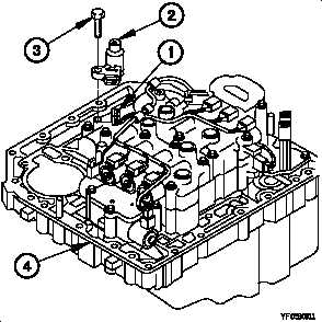
a. Removal.
(1) Disconnect wiring harness connector (1) from turbine
speed sensor (2).
(2) Remove two screws (3) and turbine speed sensor (2)
from control valve module (4).
b. Installation.
NOTE
Handle parts carefully to prevent damage.
(1) Position turbine speed sensor (2) on control valve
module (4) with two screws (3).
(2) Tighten two screws (3) to 108-120 lb-in. (12-14 N·m).
(3) Connect wiring harness connector (1) to turbine speed
sensor (2).
c. Follow-On Maintenance.
Install control valve module (para 7-10).
End of Task.
6-32
Integrated Publishing, Inc. - A (SDVOSB) Service Disabled Veteran Owned Small Business