TM 9-2320-365-10
Section I. DESCRIPTION AND USE OF OPERATOR’S
CONTROLS AND INDICATORS
2-1. INSTRUMENT PANEL CONTROLS AND INDICATORS
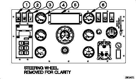
a. Instrument Panel. Figure 2-1 shows all controls and indicators on the Instrument
Panel.
Figure 2-1. Instrument Panel Controls and Indicators
1. Radiator Fan Off Switch.
When positioned to on, radiator fan off switch will
illuminate to indicate the radiator fan is disabled. Radiator fan off switch will remain
in the off position and not illuminated, unless otherwise directed.
2. Lamp Test Switch. Tests the lights on high engine temperature and TRANS OIL
TEMP indicators on Lighted Indicator Display.
3. Ether Start Switch. Injects ether into engine intake system to assist with cold
weather starting when switch is pressed.
4. FRONT BRAKE AIR Pressure Gage. Shows air pressure (in psi) available to
operate front brakes. Normal air pressure range is 65-120 psi (448-827 kPa).
5. Lighted Indicator Display. Indicator lights to indicate operating characteristics of
the vehicle. Figure 2-2 shows all indicators on the Lighted Indicator Display.
6. OIL PRESS Gage. Shows engine oil pressure (in psi). Normal oil pressure range
is 15-80 psi (103-552 kPa).
Change 1
2-3