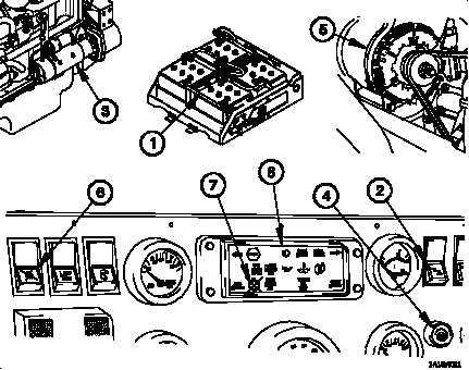
TM 9-2320-365-101-18. ELECTRICAL SYSTEMFigure 1-13. Electrical SystemThe vehicle Electrical System is a combined 12/24 vdc system. Four 12-volt batteries (1,Figure 1-13) are connected in series-parallel with the negative terminal grounded to thevehicle chassis.(1) Positioning the master power switch (2) to on applies power to all electrical circuitsneeded to operate the vehicle.(2) The starting motor (3) operates directly from the 24 vdc source through the starterpushbutton (4).(3) A 12/24-volt belt-driven alternator (5) with a 100 amp capacity maintains the chargeon the batteries. The 24 vdc source supplies electrical power to operate the startingmotor, CTIS, fuel/water separator, air dryer, ether injection system, instrument panelgages, and windshield wipers/ washer. The 12 vdc source supplies electrical power tothe vehicle lights and instrument panel lights.(4) The radiator fan off switch (6) is used to keep the radiator fan from engaging. Thefan off indicator (7) will illuminate on the lighted indicator display (8) when the radiatorfan is disabled.1-40 Change 1
Integrated Publishing, Inc. - A (SDVOSB) Service Disabled Veteran Owned Small Business