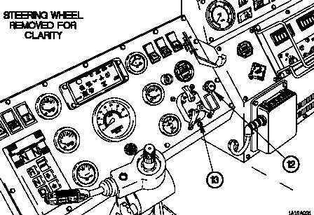
TM 9-2320-365-101-18. ELECTRICAL SYSTEM (CONT)Figure 1-13. Electrical System (Cont)(8) A dimmer switch (12) is provided so that you can adjust the brightness of theinstrument panel lighting.(9) The main light switch (13) is the only switch that is active even when the masterpower switch is off.a. Positioning the main selector lever to SER DRIVE causes the headlights, taillights,marker lights, and clearance lights to illuminate; stoplights will illuminate when brakepedal is depressed.b. Positioning the main selector lever to STOP LIGHT extinguishes all vehicle lightsbut allows stoplights to illuminate when brake pedal is depressed.c. Positioning the auxiliary lever to PARK with the main selector lever in SER DRIVEcauses the headlights to extinguish and the front parking lights to illuminate.d. Positioning the main selector lever to BO MARKER causes the blackout markerlights to illuminate.e. Positioning the main selector lever to BO DRIVE causes the blackout drive lightand blackout marker lights to illuminate.f. Instrument panel lights are illuminated when the main selector lever is in BRTposition.1-42
Integrated Publishing, Inc. - A (SDVOSB) Service Disabled Veteran Owned Small Business