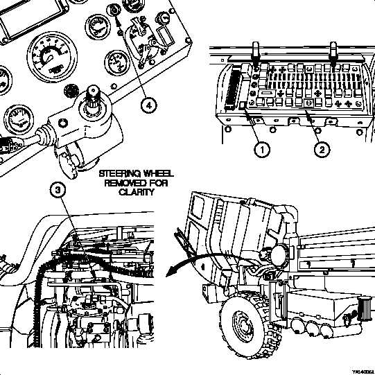
TM 9-2320-365-34-1g. Indicator Lights and Alarms. The lighted indicator display (9) and audible alarm (10), located on the instrumentpanel assembly, are activated by switches located in various systems. These include, but are not limited to; masterstop, low engine oil pressure, low air pressure, high water temperature, engine fan off, and high transmission oiltemperature. When any of these switches are activated, they energize the proper indicator and/or alarm, alerting theoperator of a potential problem or condition which needs to be monitored.Figure 1-14. Troubleshooting Aidh. Troubleshooting Aid. A start inhibit switch (1, Figure 1-14), located on the Power Distribution Panel (PDP) (2),is provided as a troubleshooting aid for the Unit and DS Maintenance levels and as a maintenance tool at the GSMaintenance level to stop fuel flow at the fuel shutoff solenoid (3). By pressing the start inhibit switch first, the starterpushbutton (4) can be pressed and the engine cranked without allowing the engine to be started. The start inhibitswitch is reset when the master power switch is positioned to off and then to on again.Change 1 1-19
Integrated Publishing, Inc. - A (SDVOSB) Service Disabled Veteran Owned Small Business