TM 9-2320-365-34-1
D-5. CAB SUPPORT TOOL (CONT)
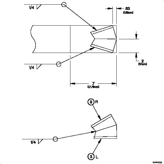
Figure D-13. Cab Support Tool Seat Layout
h. Position and clamp cab support tool seats (3) L and (3) R together as shown by dimensions in Figure D-13. Cab
Support Tool Seat Layout.
i. Weld cab support tool seat (3) L to cab support tool seat (3) R as identified in assembly table and Figure D-13.
Cab Support Tool Seat Layout.
j. Position and clamp cab support tool seats (3) L and (3) R to cab support tool strut (1) as shown by dimensions
in Figure D-4. Cab Support Tool Seat Layout.
k. Weld items clamped in step (j) as shown in Figure D-4. Cab Support Tool Seat Layout.
l. De-burr and remove sharp edges.
D-18