TM 9-2320-365-34-2
21-15. C7 CLUTCH HOUSING AND FRONT OUTPUT HOUSING ASSEMBLY REPAIR
This task covers:
a. Disassembly
b. Cleaning/Inspection
c. Assembly
d. Follow-On Maintenance
INITIAL SETUP
Equipment Conditions
Transfer case module disassembled (para 22-3).
Tools and Special Tools
Tool Kit, Genl Mech (Item 68, Appendix B)
Puller Kit, Universal (Item 44, Appendix B)
Indicator, Dial (Item 30, Appendix B)
Inserter, Bearing and Bushing (TM 9-2320-365-20)
Inserter, Bearing and Bushing (TM 9-2320-365-20)
Inserter, Bearing and Bushing (TM 9-2320-365-20)
Inserter, Bearing and Bushing (TM 9-2320-365-20)
Handle, Drive (TM 9-2320-365-20)
Caliper, Vernier (Item 8, Appendix B)
Press, Arbor, Hand Operated (Item 41, Appendix B)
Tools and Special Tools (Cont)
Puller Kit, Universal (Item 43, Appendix B)
Gage Set, Telescoping (Item 21, Appendix B)
Pliers, Retaining Ring (Item 37, Appendix B)
Goggles, Industrial (Item 25, Appendix B)
Gloves, Rubber (Item 23, Appendix B)
Materials/Parts
Sealring (Item 284, Appendix F)
Sealring (Item 285, Appendix F)
Seal, Plain Encased (Item 265, Appendix F)
Sealring (3) (Item 286, Appendix F)
Lubricating Oil, Engine (Item 45, Appendix C)
Rag, Wiping (Item 59, Appendix C)
Solvent, Dry Cleaning (Item 81, Appendix C)
a. Disassembly.
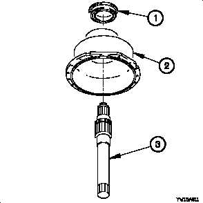
(1) Remove oil seal (1) from front output housing (2).
Discard oil seal.
(2) Remove front output shaft (3) from front output housing
(2).
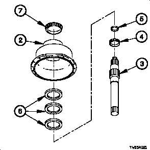
(3) Remove roller bearing cone (4) from front output shaft
(3).
(4) Remove spacer (5) and shim(s) (6) from front output
shaft (3).
(5) Remove roller bearing cone (7) from front output housing
(2).
21-70