TM 9-2320-365-34-2
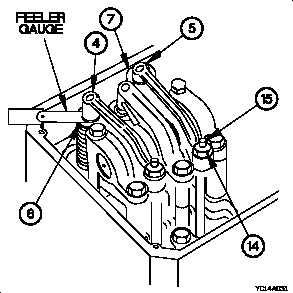
(10) Refer to Table 3-2 Valve Clearances and insert a feeler
gauge of correct dimension between intake rocker arms
(4) or exhaust rocker arms (5) and their respective
valves (6 or 7).
Table 3-2. Valve Clearances
VALVES
GAUGE DIMENSIONS
Intake
0.015 in. (0.38 mm)
Exhaust
0.025 in. (0.64 mm)
(11) Turn adjustment screw (15) clockwise until either valve
(6 or 7) is set to specifications in Table 3-3 Valve
Clearance Ranges.
Table 3-3. Valve Clearance Ranges
VALVES
ACCEPTABLE CLEARANCE RANGE
Intake
0.012 - 0.018 in. (0.30 - 0.46 mm)
Exhaust
0.022 - 0.028 in. (0.56 - 0.72 mm)
(12) After each adjustment, tighten jam nut (14) to 156-276
lb-in. (17-31 N·m).
(13) Perform steps (5) through (12) on remaining valves on
that stroke.
NOTE
•
Perform step (14) after checking and
adjusting clearance on all valves for a
specified piston position.
•
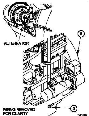
Use bolt on front of alternator to rotate
flywheel for timing bolt installation
(14) Rotate flywheel right 360 degrees.
(15) Remove timing bolt (3) from timing bolt hole on front of
flywheel housing (2).
(16) Rotate crankshaft 360 degrees.
(17) Install timing bolt (3) in timing bolt hole on front of
flywheel housing (2).
NOTE
This will put number 1 piston at top center
(TC) position on the other stroke.
(18) Perform steps (3) through (5) on remaining valves.
3-103