TM 9-2320-365-34-2
(l)
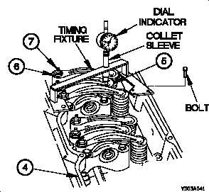
Hold collet sleeve up and gently install dial indicator
and timing fixture in position on inlet manifold (4)
over injector to be checked.
NOTE
• When properly positioned, locating pin and bolt
will engage holes in top face of inlet manifold.
• The sliding locating pin and two hole positions
are provided in the timing fixture because of a
different valve cover bolt hole position on the
rear cylinder.
(m) Install bolt to secure timing fixture to inlet manifold
(4).
(n) Slide collet sleeve until long pin of timing fixture
contacts shoulder of injector (5).
(o) Verify dial indicator reads 0.00 mm 0.20 mm.
NOTE
• If dial indicator reading is within limits proceed to
step (7).
• If dial indicator reading is NOT within limits,
perform steps (4p through 4s).
• The limits are a checking tolerance.
If
adjustment is necessary, adjust each injector to
the specified fuel timing dimension.
(p) Loosen locking nut (6) on push rod adjustment
screw (7) for injector (5) to be adjusted.
(q) Turn adjustment screw (7) until dial indicator reads
0.00 mm.
(r) Tighten self-locking nut (6) on adjustment screw (7)
to 13-23 lb-ft (18-32 N m).
(s) Check adjustment again.
(t) Perform steps (4o through 4s) until adjustment is
correct.
4-21