TM 9-2320-365-34-2
7-12. MAIN VALVE BODY ASSEMBLY REPAIR
This task covers:
a. Disassembly
b. Cleaning/Inspection
c. Assembly
d. Follow-On Maintenance
INITIAL SETUP
Equipment Conditions
Control valve module disassembled (para 7-11).
Tools and Special Tools
Tool Kit, Genl Mech (Item 68, Appendix B)
Multimeter, Digital (Item 34, Appendix B)
Caliper, Vernier (Item 8, Appendix B)
Wrench, Torque, 0-60 N·m (Item 84, Appendix B)
Wrench Set, Socket (Item 75, Appendix B)
Press, Arbor, Hand Operated (Item 41, Appendix B)
Spring Compression Tool, Main Valve Body (Item 11,
Appendix D)
Tools and Special Tools (Cont)
Goggles, Industrial (Item 25, Appendix B)
Gloves, Rubber (Item 23, Appendix B)
Materials/Parts
Rag, Wiping (Item 59, Appendix C)
Packing, Preformed (Item 177, Appendix F)
Packing, Preformed (Item 175, Appendix F)
Filter Element (Item 25, Appendix F)
Solvent, Dry Cleaning (Item 81, Appendix C)
Dispenser, Pressure Sensitive Adhesive Tape
(Item 31, Appendix C)
a. Disassembly.
CAUTION
The main valve body contains parts which
cannot be interchanged. Tag all parts prior
to removal. Failure to comply may result in
damage to equipment.
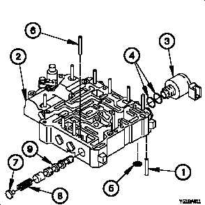
(1) Remove retaining pin (1) from main valve body (2).
(2) Remove solenoid (3) from main valve body (2).
(3) Remove two preformed packings (4) from solenoid (3).
Discard preformed packings.
(4) Remove solenoid filter screen (5) from main valve
body (2). Discard solenoid filter screen.
WARNING
Use care when removing springs.
Springs are under tension and can act
as projectiles when released. Failure to
comply may result in injury to
personnel.
(5) Remove retaining pin (6), stop (7), spring (8), and C2
latch valve (9) from main valve body (2).
7-81