TM 9-2320-365-34-2
(20) Wipe away any excess lubricant or sealing compound
that may be in either injector sleeve bore (1) or in
injector sleeve (3).
NOTE
Use large bushing (identified by an "L" or by
a coarse knurl) if it will slip into bore with
hand force.
If large bushing can not be
installed as stated, select smaller bushing
(identified by an "S" or a fine knurl).
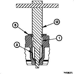
(21) Install guide bushing (5) in injector sleeve bore (1).
(22) Apply a generous amount of engine oil to lubricate the
cutting area of the reamer assembly (12).
(23) Install reamer assembly (12) in guide bushing (5).
NOTE
•
Reamer assembly will cut aggressively.
•
Check cutting progress often. Stop cutting when
injector seat is full faced or when shoulder of
reamer assembly comes in contact with guide
bushing.
•
If injector seat does not match to 360 full face,
injector sleeve must be removed. Install new
injector sleeve and do reaming procedure again.
•
Stop cutting immediately when seat is full face,
so minimum amount of material is removed.
This way, as much material as possible will be
retained, in the event that reaming is necessary
in the future.
•
For correct sealing of combustion gas, injector
seat must be free of machining chatter and
scratches.
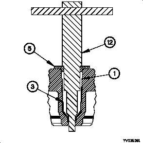
(24) With light but even pressure, turn reamer assembly (12)
to right.
(25) Remove reamer assembly (12) and guide bushing (5)
from injector sleeve bore (1).
(26) Remove any evidence of lubricants or copper particles
that may be in, or on, injector sleeve (3). Be sure to
thoroughly clean cylinder head fuel galleys.
20-21