TM 9-2320-365-34-2
17-2. SUSPENSION CYLINDER REPLACEMENT
This task covers:
a. Removal
b. Installation
c. Follow-On Maintenance
INITIAL SETUP
Equipment Conditions
Engine shut down (TM 9-2320-365-10).
Cab raised (TM 9-2320-365-10).
Top radiator fan shroud removed (TM 9-2320-365-20-
3). (LH side only).
Engine front resilient mounts removed (para 3-4). (LH
side only).
Tools and Special Tools
Tool Kit, Genl Mech (Item 68, Appendix B)
Goggles, Industrial (Item 25, Appendix B)
Gloves, Rubber (Item 23, Appendix B)
Wrench, Torque, 0-175 lb-ft (Item 80, Appendix B)
Wrench, Torque, 0-600 lb-ft (Item 85, Appendix B)
Wrench, Torque, 0-200 lb-in. (Item 81, Appendix B)
Tools and Special Tools (Cont)
Socket Set, Socket Wrench (Item 34, Appendix
B)
Wrench Set, Socket (Item 74, Appendix B)
Materials/Parts
Cap and Plug Set (Item 18, Appendix C)
Packing, Preformed (2) (Item 212, Appendix F)
Nut, Self-Locking (Item 145, Appendix F)
Pin, Cotter (Item 226.1, Appendix F)
Hydraulic Fluid A (Item 41.2, Appendix C)
Personnel Required
(2)
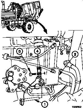
a. Removal.
NOTE
Left and right suspension cylinders are
removed the same way. Right side shown.
(1) Remove two quick release pins (1) from suspension
cylinder (2).
(2) Remove screw (3) and two lanyards (4) from suspension
cylinder (2).
17-2
Change 1