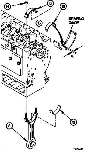
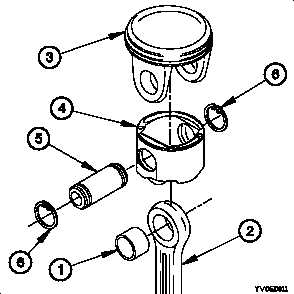
TM 9-2320-365-34-2CAUTIONDo not turn crankshaft while bearing gage ison connecting rod bearing. Failure to complywill result in inaccurate clearance reading andpossible damage to equipment.(29) Remove two connecting rod cap nuts (14) andconnecting rod (3) from rod cap (5).(30) Remove rod cap (5) from connecting rod journal (13).(31) Measure greatest width (A) of bearing gage inconnecting rod bearing half (12) against chart containedin gage package. Maximum clearance is 0.0061 in.(0.015 cm). Record clearance reading.(32) Clean bearing gage from connecting rod half (12) andconnecting rod journal (13).(33) Perform steps (19) through (32) for remaining fiveconnecting rods and rod caps.d. Assembly.(1) Install piston rod bearing (1) in connecting rod (2).(2) Install piston crown (3) on piston skirt (4).(3) Install piston crown (3) on connecting rod (2) with pistonpin (5).WARNINGUse care when installing retaining rings.Retaining rings are under tension and canact as projectiles when released. Failureto comply may result in injury topersonnel.(4) Install two retaining rings (6) on piston pin (5).20-47
Integrated Publishing, Inc. - A (SDVOSB) Service Disabled Veteran Owned Small Business