TM 9-2320-365-34-2
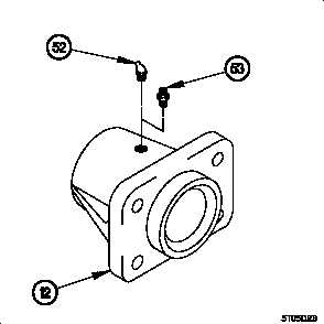
(26) Remove 45-degree grease fitting (52) from support (12).
(27) Install grease fitting (53) in support (12).
NOTE
• Use bolts P/N 12414307-142 and self-locking
nuts P/N 12414308-025 on step (28).
• Support will be installed with fitting facing down.
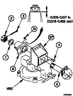
(28) Position support (12) on pintle hook extension (37) with
four bolts (11) and self-locking nuts (10).
(29) Position pintle hook extension (37) in vise.
(30) Tighten four self-locking nuts (10) to 196-240 lb-ft (265-
325 N·m).
(31) Position pintle hook (8) in pintle hook extension (37) with
washer (7) and nut (6).
CAUTION
Clearance between washer and support must
be 0.003-0.017 in. (0.076-0.432 mm). Failure
to comply may result in damage to
equipment.
(32) Adjust nut (6) until clearance is 0.003-0.017 in. (0.076-
0.432 mm) with alignment holes lined up between nut (6)
and pintle hook (8).
(33) Install cotter pin (5) in nut (6).
Change 1
18-7


